


Roll over image to zoom in
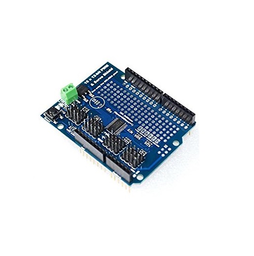
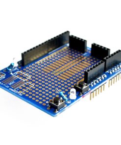
Servo Driver Module Shield 16 Channel
₹525.00 (excl. GST)
Features :
- The I2C input, PWM output control 16 roads, steering gear can 16 roads.
- The steering gear power independent V + input maximum 6 V.
- Logic signals and logical power independent output for 3V to 5 V.
- 40-1000 Hz frequency.
Description
Servo Driver Module Shield
You want to make a cool robot, maybe a hexapod walker, or maybe just a piece of art with a lot of moving parts. Or maybe you want to drive a lot of LEDs with precise PWM output. Then you realize that your microcontroller has a limited number of PWM outputs! Here is the Servo Driver Module Shield 16 Channel to help you out.
You could give up OR you could just get our handy PWM and Servo Driver Module Shield. It’s now Arduino-ready and works with any Arduino that uses shields: Uno, Mega, ADK, it’s all good.
Using only two pins, control 16 free-running PWM outputs! You can even chain up 62 breakouts to control up to 992 PWM outputs
- Servo Driver Module Shield is an I2C-controlled PWM driver with a built-in clock. That means that, unlike the TLC5940 family, you do not need to continuously send it the signal to tie up your microcontroller, it’s completely free running!
- Servo Driver Module Shield is 5V compliant, which means you can control it from a 3.3V microcontroller and still safely drive up to 6V outputs (this is good for when you want to control white or blue LEDs with 3.4+ forward voltages)
- 6 address select pins so you can wire up to 62 of these on a single i2c bus, a total of 992 outputs – that’s a lot of servos or LEDs
- Adjustable frequency PWM up to about 1.6 KHz
- 12-bit resolution for each output – for servos, that means about 4us resolution at a 60Hz update rate
- Configurable push-pull or an open-drain output
- The output enable pin to quickly disable all the outputs
We wrapped up this lovely chip into a breakout board with a couple of nice extras
- Terminal block for power input (or you can use the 0.1″ breakouts on the side)
- Reverse polarity protection on the terminal block input
- Green power-good LED
- 3 pin connectors in groups of 4 so you can plug in 16 servos at once (Servo plugs are slightly wider than 0.1″ so you can only stack 4 next to each other on 0.1″ header
- “Chain-able” design
- A spot to place a big capacitor on the V+ line (in case you need it)
- 330-ohm series resistors on all the output lines to protect them, and to make driving LEDs trivial
- Solder jumpers for the 6 address select pins.
Specification
Additional information
| Weight | 105 g |
|---|---|
| Dimensions | 7 × 5 cm |
| No. of Channels | 16 |
| Resolution | 12 |

Reviews
There are no reviews yet.